

SCART Connectors & Connections
In the good old days, the back of the TV set had only one socket on it - for the TV aerial - and SCART sockets (and all the other alternatives) didn’t exist.
Since then, things have changed a bit, and new digital ready TVs have lots of sockets on the back of the set, with a heavyweight user guide to explain things. Some of these details can be rather daunting, and alternative connection diagrams may only available via the manufacturer's web pages.
Some of the mysteries of SCARTs are explained in the following sections.
SCARTS & VCRs
After the invention of the video recorder, SCART sockets were introduced on both TVs and video recorders (VCRs), giving stereo sound (with a NICAM VCR) and helping (a little) with picture quality by avoiding the conversion of the recorded programme to UHF (in the VCR's modulator) and back again to video in the TV set:
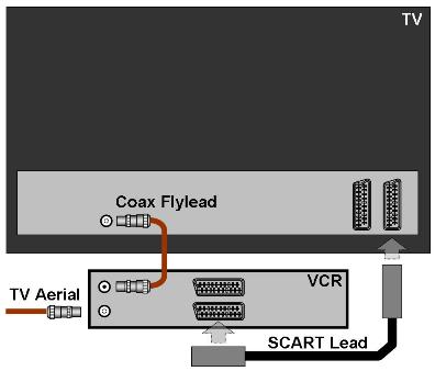
The TV aerial connects into the VCR first - this is necessary since the VCR has its own UHF tuner (so it can record a programme different to the one being watched on the TV). A coax flylead is then used to connect from the VCR to the TV aerial input. The UHF signals from the aerial are "looped through" the VCR (sometimes with a small amount of gain).
Prior to NICAM stereo, SCART leads didn’t exist, and the VCR was connected to the TV only with the coax flylead. Inside the VCR, a UHF modulator creates an additional UHF "channel" which is combined with the signals already in the TV aerial lead. This requires the TV set to be tuned to the usual stations (BBC1, 2, ITV, CH4 & Five) and additionally to the "VCR channel" (frequently on "program 5 or 6"). By default, VCRs were often set to channel 36, but this setting sometimes needed to be changed to avoid interference with the TV signals.
The UHF modulator in the VCR gives two limitations:
| 1) The recorded video is degraded slightly by converting it to UHF and then back again to video in the TV. |
| 2) The sound reproduction is mono |
Even if a NICAM stereo VCR is used, replaying via the UHF flylead will give mono sound. This is where the SCART lead becomes useful.
With a SCART interface however, the TV either has to be "told" to use it (via the remote control TV:A/V button) or automatically "know" when the video (A/V) signal is present. Most TVs and VCRs use a dedicated pin in the SCART connector to signal the A/V command to the TV, which makes the TV switch over to using that SCART socket when the VCR is set to "play".
N.B. On some TVs, pressing e.g. "program 1" (for BBC1) on the remote control will make the TV revert back to that programme, despite the video signal (and the auto switching signal) still being present on the SCART socket. However, some TVs don’t allow the TV to revert back while the SCART socket (and auto switching signal) is present.
Using the SCART lead bypasses the UHF modulator in the VCR and avoids any degradation of the video signal, and also maintains stereo sound (with a NICAM capable VCR).
The SCART lead carries left and right sound channels and also carries "video" from the VCR to the TV. At this stage things seem simple enough, but the SCART interface contains some additional functions (or complications depending on your point of view!).
Modern TV A/V Sockets & Interfaces
To appreciate the SCART functionality, it’s worth considering the different interfaces available on the back of a modern TV set. The following photographs show a Toshiba set, with an array of different sockets, for lots of different items of equipment:
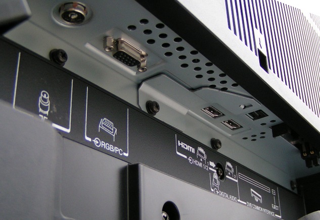
The top photograph shows (from left to right):
| UHF aerial socket. |
| RGB / PC (VGA) socket for connection to a personal computer. |
| HDMI sockets (for high definition video from a DVD player or satellite receiver). |
| Digital audio output (S/PDIF) socket for connection to a surround sound system. |
| DVB common interface (PCMCIA) port to allow a conditional access module to be used to decode scrambled (subscription) channels. |
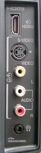
The left-hand photo above shows the sockets at the side of the TV set:
| HDMI socket (as above). |
| S video (4 pin mini-DIN) socket for connection to e.g. a camcorder. |
| Composite video (yellow RCA phono) and stereo sound (white & red RCA phono) for connection to e.g. a camcorder. |
| Stereo headphone socket |
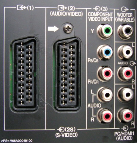
The right-hand photo above shows the remaining sockets on the back of the TV set:
| SCART (RGB) socket for connection to e.g. a satellite receiver. |
| SCART (S video) socket for connection to a media recorder or VCR. |
| Component video (RCA phono) sockets for connection to e.g. a DVD player. |
| PC / HDMI audio inputs & outputs (L + R) and a connection for an "active super woofer" for improved bass. |
Working through these connections, various different kinds of "video" are evident. These are:
| HDMI (high-definition multimedia interface) |
| RGB (red, green, blue) |
| Component video (Y = luminance, PB/CB = blue signal, PR/CR = red signal) |
| S Video (separate video i.e. chrominance & luminance) |
| Composite video (CVBS, composite video blanking and sync.) |
The HDMI interface is the only digital interface in this list - both the video and sound signals are digital, and hence the connecting lead (4 screened twisted pairs plus a few additional wires) is significantly different to the others.
RGB uses three independent wires to carry the signal for each of the three colours (red, green & blue). On their own, these three wires still cannot combine to make a complete TV picture, since they require the addition of the sync. signal (typically extracted from the composite video signal pin) in the SCART interface. Because the three colour signals are kept separate, RGB should give a good quality picture.
Component video is a more efficient way of connecting the analogue picture information than the RGB interface, since it avoids the repetition of the luminance signals. Instead, component video sends the luminance signal (Y) and sync. on one wire, and two of the colour signals on a further two wires. The third colour signal is calculated from the other two colour signals. Component video is capable of carrying high definition (HD) pictures, and should be able to match an HDMI connection, up to the TV's maximum resolution available (often 1080i but not necessarily 1080p via the component video interface).
S video divides the video into a chrominance (colour) signal, and a luminance (brightness) signal which are carried on two separate wires. Keeping these signals separate helps to maintain the image quality, but S video is significantly inferior to either Component video or RGB. S video is just video - it requires a separate cable to carry the L & R sound channels.
CVBS / Composite video uses just one wire to carry the combined colour, brightness and sync. signals for a video image. This form of video gives the lowest overall picture quality through a SCART lead - it is typically used by domestic VCRs. The yellow RCA connector in the photo above (just above the L & R audio connectors) is a composite video input for e.g. a camcorder.
Having established that video signals can have a number of different formats (which differ in terms of image quality), we can get back to the SCART interface specifically.
SCART leads and interfaces are the most commonly used method to connect Freeview tuners and satellite receivers, and can be the cause of much confusion and frustration with TV operation, requiring a significant amount of time to resolve (mostly spent reading the various user manuals supplied trying to discover the correct menu option required).
The complication with SCARTs isn’t helped by the Digital Switchover - most people will need to use a SCART interface with new digital equipment, and may need to use different / unfamiliar buttons on their remote control(s).
SCART Lead Pin Assignments & Functions
The SCART interface is inherently complicated, all on its own; hence some detail of what’s inside it may help:
Inside a fully wired SCART lead, the pin to pin connection diagram looks like this:-
The crossed wire pairs are for specific inputs and outputs, to enable the same lead to work in both directions (e.g. VCR to TV and TV to VCR), and for the SCART lead to be reversible (i.e. it doesn’t require a designated "input" or "output" end).
* Pins 17 and 18 can be straight through (17-17 & 18-18) connections in some leads, but occur crossed (17-18 & 18-17) in others.
(Many thanks to Ralf Clumb for highlighting this).
The large number of connections contributes to the lead being fairly thick and heavy, and since the SCART connector is held in place mostly be the friction of the individual connector pins and sockets, connection troubles such as lack of sound (pins 1 & 2 disconnected) or lack of picture (pins 19 & 20 disconnected) can often be restored by pushing the connector back in to the socket fully.
Individual pins in the SCART connector can sometimes "slip" back into the connector, resulting in a bad connection. This can often be fixed simply by pulling the pin with fine-nosed pliers back to its proper position.
The SCART lead carries stereo sound (L & R audio), but it also has lots of other functions:
A/V select (pin 8)
A/V is an abbreviation for audio / visual, and is a term used to signify a signal input on any of the external input sockets at the back of the TV. The TV can be regarded as either being in "TV" mode (i.e. using its internal tuner), or in "A/V" mode (i.e. using the video signal from another source).
This pin is used by items such as VCRs, DVDs, Freeview receivers etc. to automatically "switch" the TV to use the video signal on that particular SCART connector. This is achieved with either a "high" voltage level (9.5 to 12V = "A/V" mode) or a low voltage level (0 to 2V = "TV" mode).
Some Freeview receivers will set automatically switch the TV to "A/V" as soon as they are switched on. Menu options may be available on either the TV or the remote equipment (or both) to enable or disable the A/V "auto" function (TV setup menus can be quite extensive - consult the user manual if all else fails).
Some items of Freeview equipment have been known to send out occasional spurious A/V signals when in standby mode, resulting in a blank screen on the TV set for no apparent reason if the A/V "auto" switching option is operating.
Many TV sets will return to TV mode when e.g. "programme 1" is selected on the remote control, despite having the A/V signal still applied to the SCART connector, but some TV sets that "auto" switch to A/V will remain there with no means of disabling this function. To return to TV mode would then require either the A/V equipment to be switched off, or the SCART lead to be unplugged. One fix for this is to modify the SCART lead to remove pin 8 (or its wired connection).
TVs with more than one SCART socket do not necessarily have "auto" A/V switching provided on every SCART connector - check the A/V menus to determine if the function is present and whether it is enabled or not. "Auto" A/V switching with multiple boxes (DVD, satellite receiver, media recorder etc.) can become confusing - many modern TV sets allow a particular external input to be "named" to help identify what’s actually being viewed. This can also help when manually selecting a required input using the remote control.
Comms Data
Some TV sets (e.g. Sony) provide a communication link between the TV and e.g. a VCR, so that re-tuning the analogue TV channels also automatically updates the VCR tuning (works well in practice). This feature tends to be used only between items of equipment from the same manufacturer that have been designed to work together.
Composite (CVBS) Video
As described further up this page, composite video is the default standard for VCRs, where the degradation in picture quality from combining video, blanking and sync signals doesn’t make the picture any worse than the original VHS recording on the tape.
With a Freeview receiver (or a satellite receiver), the digital picture quality will be noticeably degraded using composite video, compared with viewing using the RGB interface.
RGB Video Signals
Six of the SCART connector pins are dedicated for the individual red, green and blue signals (and their corresponding ground connections). Keeping the colour signals separate and independent minimises signal degradation (provided screened leads are used) and should give a noticeable improvement in picture quality compared with using composite video.
A "fully wired" SCART lead has every pin connected, but SCART leads that are "thin" may be missing the RGB connections (which would still enable the lead to work with a VCR using the Composite video pin).
Understanding the different types of video format (for the same image) in a SCART lead can seem confusing, which isn't helped by the multiple menu options for both the source (e.g. Freeview box) and the TV, and by the alternative types of SCART lead available:
| Source video output (menu access): | Composite or RGB | |
| TV SCART input (menu access): | RGB or CVBS | |
| TV SCART input (menu access): | S video or CVBS | |
| TV SCART socket: | RGB / S video / CVBS | |
| SCART lead options: | Fully wired (thick) or partially wired (thin - Composite video only) |
The actual options for all of these items can vary significantly, and depends on the actual equipment being used - it's essential to have the user guide available for each item of equipment, and to have each original remote control rather than a "universal" remote (which may not be able to access the necessary menu options).
SCART Connection Diagrams
For the simplest Freeview box or satellite receiver setup, the connection diagram looks almost identical to the VCR diagram above:
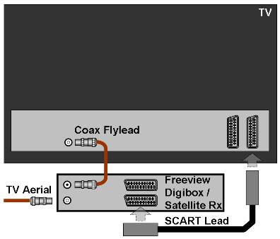
As before, the TV aerial is connected to the Freeview box first, and then the coax flylead connects to the TV aerial input.
A few Freeview boxes incorporate a UHF modulator (e.g. the Humax F2-FOX T), which can then be used without a SCART lead (handy if your TV doesn’t have a SCART socket!). Most Freeview boxes don’t include a UHF modulator.
For watching digital TV only, the coax flylead is not required - its sole purpose is to "loop through" the analogue TV signals to the TV set.
The SCART lead should be connected to an RGB capable socket. On the Toshiba TV photos shown above, this would be SCART (1). Consulting the user guide for the TV may be necessary to determine which SCART sockets have RGB functionality (and which do not).
With satellite receivers & Sky boxes, an RF modulator is typically included to enable a remote TV to be supplied with the current satellite TV program. This is the same type of UHF modulator as fitted to VCRs, and has the same limitations, being an analogue signal with mono sound. As with Freeview receivers, using the SCART socket to connect to the main TV and selecting the RGB video option will give the best picture quality.
With the SCART lead connected, check the picture quality whist looking at a menu screen - Composite video gives slightly less sharp edges compared to RGB - check the menu settings for both the digibox and the TV to verify they are both set to RGB.
Adding a VCR can be done in two different ways - the preferred arrangement will depend on individual equipment and how it is used.
The first diagram below uses an additional SCART socket on the TV, but this does not need to be RGB capable since the VCR only outputs Composite video. Using the Toshiba TV example, the VCR would connect to SCART (2):
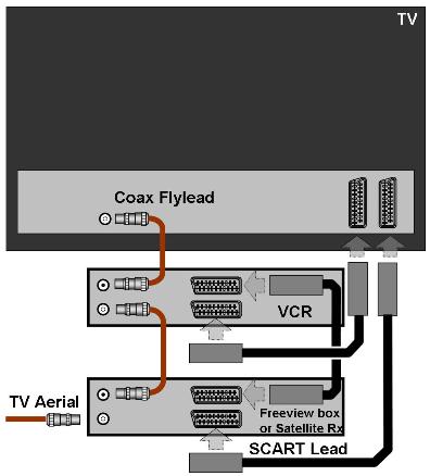
With the SCART sockets connected as above, the TV needs to be able to select either of the SCART inputs as required. Different TVs have different options with multiple SCART inputs - some allow auto switching on just one SCART, while others may allow it on all SCARTS (possibly with the option to disable this in the menu). Manually switching between the SCART sockets can be done using the TV remote control, and may require pressing the appropriate button (e.g. Ext 1, Ext2) or pressing and holding a menu button to bring up the input selection menu.
In addition to selecting the correct "input" for the TV, the VCR also needs to have its A/V input selected to be able to record from the digibox via the SCART connection. On a typical VCR, the A/V input can be accessed by counting down in channel numbers - the channel "down" from 1 should display A/V (or possibly A/V 2 for a 2 SCART VCR - choose the one that works!).
The next diagram shows how to add the VCR when only one SCART socket is available, or when the second one is required for something else:
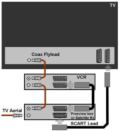
This arrangement relies on both SCART sockets on the Freeview box being fully linked.
N.B. some Freeview boxes are only wired with SCART "out" sockets - in this case, the signal coming from the VCR will not pass through the Freeview box. If this happens, connect the TV SCART on the VCR to the TV set and route the Freeview box to the AV SCART on the VCR. With the VCR set to AV input, the Freeview picture should be available on the TV (and may also be recorded on the VCR).
If the Freeview SCARTs are fully linked, the connections shown should work provided the VCR is not playing a tape when the digibox is operating (both pictures may try to mix together). The VCR can record from the digibox using this configuration - both units will operate together since the VCR doesn’t generate its own video output during recording.
Additional SCART Sockets
In addition to a Freeview box and VCR, many people want to have a DVD and possibly other items of equipment (e.g. a media recorder). The TV may not have sufficient SCART sockets to enable all these items of equipment to be connected. SCART splitter / combiner leads can be used to increase the available sockets, though these can give interference problems and picture quality degradation. Limitations on what equipment can be operated simultaneously may also be encountered.
An alternative method to provide additional SCART sockets is to use a powered SCART switcher, such as the Bluedelta SmartSCARTunit shown below:
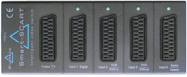
This unit accepts RGB and composite video inputs on all SCART sockets, and routes the last switched SCART socket through to the single output lead. The unit also provides an internal SCART to SCART connection between two sockets to provide the facility to record without needing an additional SCART cable. See the Bluedelta website for various connection options.
S Video SCARTs
The SCART sockets described so far have all been RGB / Composite video compatible, which on their own can create more than enough complication for many people. Looking carefully at the photos of the Toshiba TV set, we can see that there’s something "different" about the SCART 2 socket. This particular SCART is capable of transferring signals using the S video format, which is achieved by "reallocating" the conventional SCART pin functionality - specifically two of the pins allocated for the RGB signals. This means that this particular SCART 2 socket doesn’t support RGB, but it can be used for either an S video connection (to e.g. a media recorder) or for a composite video connection (e.g. a VCR).
This SCART socket may look identical to the RGB SCART socket, but functionally it is quite different. The menu settings on the TV allow this socket to be selected either as an S video socket, or as a composite video socket (but never as an RGB socket).
Effectively this gives two different types of SCART socket!
N.B. When using SCART adapters, make sure the correct adapter type is connected to the correct sort of SCART socket (e.g. a SCART to S video adapter needs to plugged into an S video SCART socket).