

Aerials & Coax
In principle, the TV aerial's job is simple - all it has to do is to pick up a signal from the transmitter and send it through a bit of coax cable to the TV set.
Five factors are necessary to achieve this:
| 1) | Sufficient signal is available from the transmitter |
| 2) | The aerial has sufficient gain and bandwidth |
| 3) | The aerial is pointing in the right direction |
| 4) | There are no interfering signals |
| 5) | The coax cable isn't lossy |
However, if the TV aerial is not right to start with, no amount of booster amplifiers will recover a usable signal.
The local signal strength for TV reception can be measured using a reference aerial and a calibrated meter. Received signal strength will be dependent on the following factors:
| 1) | The amount of power radiated from the transmitter or relay |
| 2) | The distance from the transmitter |
| 3) | Objects (hills, trees, buildings etc.) blocking the direct line of sight from the transmitter or relay to the aerial |
| 4) | Objects close to the direct line of sight, which may cause signal reflections |
If there is insufficient signal strength, then there are really only two alternatives:
| a) | Find a different location with sufficient signal strength. A different position may work better e.g. other end of the house or higher up on a longer mast. A larger aerial will give a signal increase (signal measurment will determine whether this is a feasible option). Booster amplifiers on an inadequate signal will result in a poor noise performance and give erratic digital pictures. |
| b) | Choose a different method for reception, such as satellite TV (e.g. Freesat or Sky) or Cable TV. |
If the signal strength is OK, the next step is to select a suitable aerial, which must have the correct gain and bandwidth to match the transmitter or relay.
The following table shows the full range of frequencies / channels used for UHF TV:
| Channel No. | Vision (MHz) | Sound (MHz) | Aerial Group | |||||
|---|---|---|---|---|---|---|---|---|
| A | B | C/D | E | K | W | |||
| 21 | 471.25 | 477.25 | ||||||
| 22 | 479.25 | 485.25 | ||||||
| 23 | 487.25 | 493.25 | ||||||
| 24 | 495.25 | 501.25 | ||||||
| 25 | 503.25 | 509.25 | ||||||
| 26 | 511.25 | 517.25 | ||||||
| 27 | 519.25 | 525.25 | ||||||
| 28 | 527.25 | 533.25 | ||||||
| 29 | 535.25 | 541.25 | ||||||
| 30 | 543.25 | 549.25 | ||||||
| 31 | 551.25 | 557.25 | ||||||
| 32 | 559.25 | 565.25 | ||||||
| 33 | 567.25 | 573.25 | ||||||
| 34 | 575.25 | 581.25 | ||||||
| 35 | 583.25 | 589.25 | ||||||
| 36 | 591.25 | 597.25 | ||||||
| 37 | 599.25 | 605.25 | ||||||
| 38 | 607.25 | 613.25 | ||||||
| 39 | 615.25 | 621.25 | ||||||
| 40 | 615.25 | 621.25 | ||||||
| 41 | 631.25 | 637.25 | ||||||
| 42 | 639.25 | 645.25 | ||||||
| 43 | 647.25 | 653.25 | ||||||
| 44 | 655.25 | 661.25 | ||||||
| 45 | 663.25 | 669.25 | ||||||
| 46 | 671.25 | 677.25 | ||||||
| 47 | 679.25 | 685.25 | ||||||
| 48 | 687.25 | 693.25 | ||||||
| 49 | 695.25 | 701.25 | ||||||
| 50 | 703.25 | 709.25 | ||||||
| 51 | 711.25 | 717.25 | ||||||
| 52 | 719.25 | 725.25 | ||||||
| 53 | 727.25 | 733.25 | ||||||
| 54 | 735.25 | 741.25 | ||||||
| 55 | 743.25 | 749.25 | ||||||
| 56 | 751.25 | 757.25 | ||||||
| 57 | 759.25 | 765.25 | ||||||
| 58 | 767.25 | 773.25 | ||||||
| 59 | 775.25 | 781.25 | ||||||
| 60 | 783.25 | 789.25 | ||||||
| 61 | 791.25 | 797.25 | ||||||
| 62 | 799.25 | 805.25 | ||||||
| 63 | 807.25 | 813.25 | ||||||
| 64 | 815.25 | 821.25 | ||||||
| 65 | 823.25 | 829.25 | ||||||
| 66 | 831.25 | 837.25 | ||||||
| 67 | 839.25 | 845.25 | ||||||
| 68 | 847.25 | 853.25 | ||||||
The vision and sound columns show the carrier frequencies for analogue transmission on each channel. The columns on the right-hand side of the table show the various standard aerial groups used for TV reception, which are also colour coded as indicated. The colours are used only to help identify which group an aerial belongs to - sometimes the aerial boom will have a matching coloured plastic plug fitted to its end (which may not be easy to check when it is been mounted up on a roof or chimney!).
The important feature is that aerials come in specific groups to match the frequency range of the local transmitter. The three "standard" groups (A, B, C/D) each have a bandwidth of just over 20% of their centre frequency range, and should be used (where possible) so that the aerial will give better rejection of unwanted frequencies (i.e. less interference). Most transmitters have TV channels allocated specifically to keep within one of these standard groups.
Constraints on the availability of channels and concerns about interference mean that some transmitters are not able to maintain all of the TV transmissions within one standard group. This will become the case for Beacon Hill after the digital switchover. Where this is the case, extended range or wideband aerials (E, K, and W) are available, but these aerials should only be used where necessary, as they are effectively trading off some performance in order to achieve the extended bandwidth.
Aerial Design
The standard TV aerial for domestic use is the "Yagi" aerial as shown below:
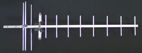
The key design features of a Yagi aerial are as follows:
The dipole is the part that converts the radiated signal from the transmitter into electrical current / voltage, and is where the electrical connections are made. The size of the dipole affects the operating frequency - higher frequencies need a shorter dipole, lower frequencies need a longer dipole (hence FM aerials are quite big). Using a folded (flattened loop shape) dipole helps to give a wider bandwidth.
Some aerials do not use a folded dipole, but have an X shaped dipole instead, which can also help to increase the operating frequency range.
The reflector is positioned at a specific distance behind the dipole, and enhances the sensitivity in the direction towards the transmitter. The reflector also reduces pickup of interference from behind the aerial. Simple aerials use a metal plate with holes to reduce wind loading, or a metal mesh. Many of the latest aerials use a V shape as a "corner reflector" to enhance the aerial sensitivity further. The reflector does not need to be solid, and can made from metal rods or tubes (aligned to the same axis as the dipole) to reduce the wind loading.
The directors along the boom are of a specific size and spacing to optimise the frequency response and sensitivity. The directors may be slightly shorter at the front of the aerial, and are spaced closer together nearer to the dipole.
The connections inside the plastic housing mounted on the dipole can appear deceptively simple:

The ends of the dipole are connected to the PCB by the two brass nuts. An F connector provides the interface to the coax cable, but the connections underneath the PCB reveal the "balun":

This is a device to match the "balanced" (i.e. symmetrical) dipole to the "unbalanced" (asymmetric, i.e. signal & earth) coax cable.
The balun provides a "half wavelength difference" (or delay) between one side of the dipole and the other. The balun in the photograph shown above achieves this with a meandering PCB track, kept in close proximity to the ground connection to maintain a characteristic impedance and phase length. The meander enables the balun to be kept physically small and also enables the impedance of the dipole to be matched to the 75 ohm impedance of the coax cable.
Baluns are important for digital reception. If the coax cable is connected directly to the ends of the dipole (as it often is in budget aerials), then the outside of the coax cable becomes part of the aerial system and can pick up stray signals or "noise". This will reduce the carrier to noise ratio, which is fundamental to good digital reception. All benchmarked aerials (with the digital tick logo) incorporate a balun for this reason.
The aerial gain is essentially a function of size - a bigger aerial will provide more signal than a smaller one, though there is a diminishing return for this. For a location close to a transmitter, a small, low gain aerial will provide ample signal. For a remote location, or one with poor reception, a bigger aerial will be essential. Gain is a relative performance comparison between the signal received by an "aerial" (a combination of dipole, reflector and directors) and the signal received by just a bare dipole alone. A dipole on its own will receive a signal level very similar to an indoor "loop" aerial on a TV. The additional elements on a Yagi aerial make it very directional - it has a much higher sensitivity, but only in a specific direction.
The small Yagi aerial shown above has a gain of about 6dB compared to a standard dipole. This is a relatively low gain. The largest domestic TV aerials have a gain of about 15dB, but are considerably larger and more expensive.
One further complication for the aerial gain is the frequency dependence. The following graph shows typical response curves for Yagi aerials in the different frequency groups:
The group A, B and C/D aerials each have an optimum centre frequency, with the performance rolling off on either side. Yagi aerials typically have a asymmetric response - the low frequency side rolls off less quickly than the high frequency side, hence the centre frequency isn't actually in the middle of the operating frequency range. The extended band and wideband aerials use an adapted version of a group C/D design, and extend the low frequency performance tail to give some response for the lower frequencies. The penalty for doing this is the significant drop in gain compared with a standard grouped aerial at low frequencies (up to 5dB) - hence these should only be used where necessary; they are not an ideal choice as a "universal" aerial.
A different style of aerial is the "grid" aerial that uses either two or four dipoles positioned in front of a reflector grid:

These aerials provide good screening from signals behind the aerial and also provide a near-flat wideband frequency response. The small mini-grid aerial shown above appears to have ceased manufacture however.
An alternative design is available for domestic TV aerials, known as a Log Periodic:
This type of aerial is somewhat different, as the design uses two main booms (forming a transmission line), with a number of dipoles distributed along its length. One half of one dipole is connected to one boom, with its matching half on the other boom:
This configuration gives a wide and flat frequency response as shown below, but with reduced gain:
The lower gain characteristic limits these aerials to areas that have a good signal strength, and makes them inappropriate for fringe areas with low signal strength.
Fringe areas can sometimes have TV channels or MUXs distributed across two standard aerial groups. For these locations, the best option may be to combine (diplex) two grouped aerials together, with each aerial giving a maximum signal from the channels that it is designed to cover. The signal combiner has to be specially configured for this purpose - using a conventional splitter / combiner is lossy and would negate the benefit achieved from having two aerials.
Although signal strength (carrier) is important, the key paramter for digital reception is the carrier to noise ratio. Noise is a term that covers anything emitting radiation in the frequency range of the aerial, or the range that the TV equipment is sensitive to. Electrical transients are one source, from e.g. fluorescent lights, central heating thermostat, fridge / freezer motor and electric drills. Interference can also come from other signals transmitted in the UHF frequency range (e.g. mobile phones and other TV transmitters / relays). All of these contributors give a certain background noise level. With noisy digital reception, errors are added to the signal which then has to rely on the error correction data bits to avoid picture degradation. Reliable reception requires both sufficient signal and an absence of interference or noise. Where interference is particularly bad, filters may need to be used to remove the unwanted signals. This can be important when using e.g. masthead amplifiers in fringe reception areas.
Aerial Poles & Brackets
Once selected, the aerial requires mounting securely. Whilst this may sound fairly trivial, putting up an aerial and mast in even a slight breeze makes the wind load effect very evident. A big aerial has more cross-section than a small aerial, so has a correspondingly higher wind loading. This is also a factor limiting the ultimate size of the aerial - fatter elements may be good for bandwidth, but they aren't good for wind loading.
Some aerial manufacturers quote figures for the wind loading in a 130km/h wind (86mph) - N.B. the loading at other speeds is proportional to the square of the wind speed. A big aerial will have a loading of 100N or more (equivalent to a 10kg / 22lb weight, but acting sideways). If this force is applied at the far end of the mounting mast it sets up substantial strain on both the mounting bracket(s) and the pole itself. For a 3m mast (10 foot), 2.5m will be above the top bracket and clamp, so the pole itself will need to be capable of sustaining a bending moment of 250Nm (100N x 2.5m). A further allowance for a safety margin means that a very substantial pole is required, with a large diameter and thick wall section. In general, steel poles are stiffer than aluminium ones, so tend to sway less in a breeze. The following graph shows calculated bending moments for steel and aluminium tube:
The steel tube works out to be just over twice as strong as aluminium for the same tube diameter and wall thickness.
Just as the pole is subject to significant loading, so are the mounting brackets. The CAI recommendation is to have 20% of the mast supported, so for a mitre chimney bracket, this equates to a maximum mast length of 1.5m (which is why so many chimney bracket mounted aerials seem to develop a bit of a "lean"). Longer poles can be used on chimneys provided two brackets can be fitted at the correct spacing. This does require the chimney stack itself to be suitably "solid".
Coax Cable
Coax cable is particularly important for an aerial installation. A length of coax cable is required to carry the received signal all the way to the TV set. Old cables with a signal loss of up to 20dB are surprisingly common, on a 20m cable length from the chimney to the TV. A 20dB loss leaves just 1% of the signal remaining - 99% has "disappeared".
Conventional coax cable looks like this:
The inner solid copper conductor is surrounded by a plastic spacer with holes running along its length. Around the spacer is the copper screening braid and over the top is the outer plastic coating (often a brown colour). The construction forms a transmission line, which is a low loss way of connecting high frequency signals. The characteristic impedance of 75 ohms is determined by the ratio of the inner conductor diameter to the outer screening braid diameter and the material properties of the plastic / air insulator. The factors that contribute to the loss are:
| 1) | Loss in the plastic / air insulator material |
| 2) | Diameter changes between the inner conductor and outer braid |
| 3) | Termination mismatch at the start or end of the cable |
| 4) | Losses inherent in the cable (from copper resistance and signal loss through the screen) |
With old coax, there can be a tendency for water ingress into the air spaces in the plastic insulator. This has a serious affect on the loss, since the water has very different material properties to air, giving signal absorption in the water and an impedance mismatch in the cable (which reflects some of the signal back to its source).
Diameter changes in the cable from tight cable bends or damage from poorly fitted cable clips also create a local impedance change, which will reflect some of the signal.
The terminations on a coax cable have to match the cable's characteristic impedance (75 ohm); hence feeding two cables from one coax socket outlet will create a mismatch, and reflect some signal back up the coax feed.
Coax cable in good condition should have a loss of about 2dB for every 10m (so measuring a loss of 20dB from aerial to TV indicates serious problems). The actual loss is frequency dependent, as the following graph shows:
Benchmarked cable with a similar diameter (6.6mm) has an almost identical loss characteristic as above. However, two advantages of a high quality cable are that it is available with a foam dielectric (so is resistant to water ingress) and it has a double screen:
The double screen helps to reduce interference pickup (through the screening braid) into the cable.
Cable routing from the aerial to the TV should be kept reasonably direct, and should avoid having sharp bends or kinks in the cable to keep the loss to a minimum. The preferred way of installing cables is to bring them down the outside of the house near to ground level and then route them horizontally to where they enter the wall (with a drip loop to stop rain getting into the house).
For a long cable run from the aerial to the TV, a masthead amplifier may be used. This should have only sufficient gain to overcome the cable loss, otherwise it can add noise and degrade the carrier to noise ratio. A masthead amplifier should only be used when there is sufficient signal from the aerial to start with, but cable loss would attenuate the signal below the minimum recommended value.
Lower loss coax cables are available - these have a larger diameter, and have a lower electrical resistance (greater surface & cross-sectional area) to reduce their loss. Conversely, thin coax cable always has a much higher loss.
Connectors
Coax connectors are the final link in the chain. Lots of different types are available:
The standard IEC connector is fitted to TV sets, videos and Freeview set-top boxes. F connectors are fitted as standard to satellite TV equipment, and are available as "screw-on", crimp or compression connectors. Screw-on connectors sometimes work loose after a time (worth checking if you're having problems). Crimps offer improved reliability, and compression connectors offer both reliability and water resistance. F type connectors use the central solid copper wire in the coax cable as the centre pin of the connector.